


Gherkin Build Log
07 Mar 2022
In December I was given 2 gherkin build kits from my friend Qlavier which came with the necessary components to build a gherkin as well as these beautiful acrylic cases which he is known for. In the following month I soldered and assembled one of the boards to be used as a macropad with a numpad as well as media controls.
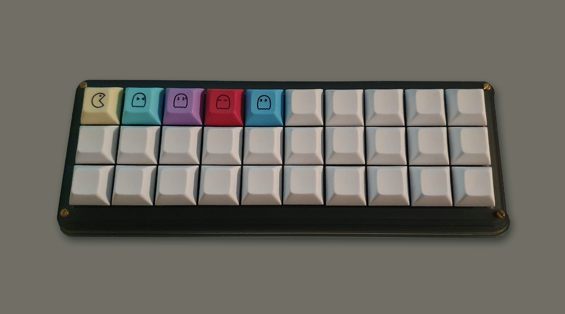 The final build
What is a gherkin
The gherkin is a 30% ortholinear open source keyboard. The 30% means it has roughly 30% of the amount of keys as a full-sized keyboard (104-108 depending on layout) meaning it has 30 keys. Ortholinear refers to the way the keys are aligned. While most regular keyboards have each row of letters slightly moved the the side of each other, ortholinear keyboards align keys in a straight grid. The keyboard is also open source as mentioned and you find all the source files for it on github.
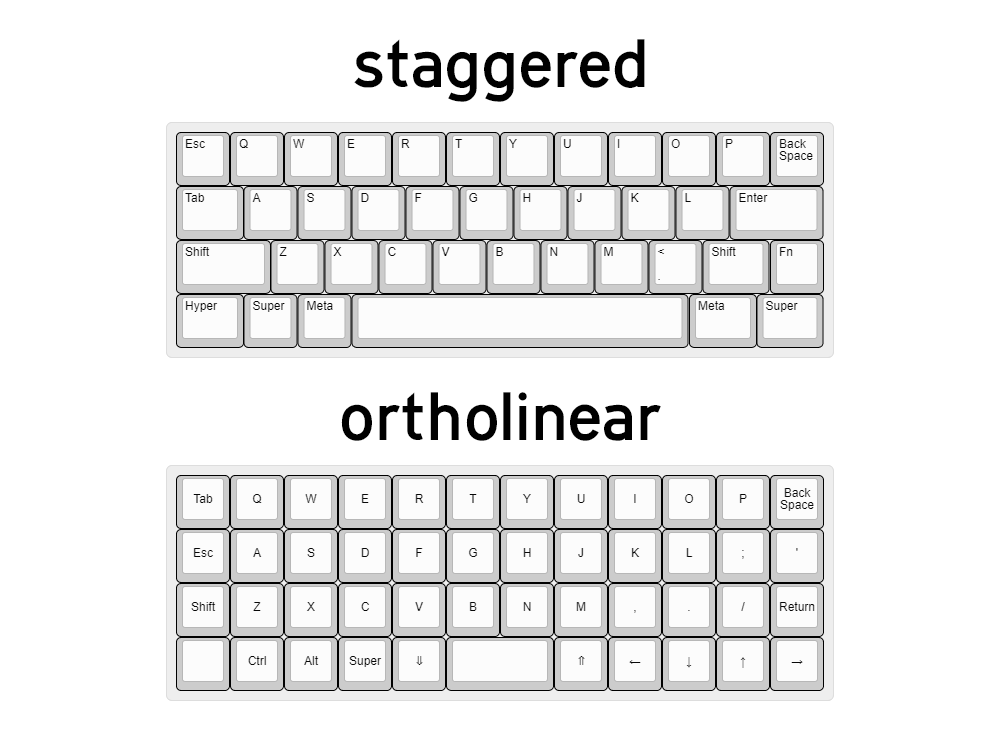 Example showing staggered and orthographic layout
Ortholinear keyboards are said to be more ergonomic because your fingers will move more easily up and down on a keyboard than side to side, while the staggered layout is a remnant from the time we used to write using typewriters. The keys were staggered so that the hammers from each of the keys wouldn’t hit each other while writing, and since then keyboards stayed that way.
About the build
When planning this build I already had in mind that I wanted to build a macropad to use for media control and other commands. I had received two boards which gave me the opportunity to try 2 different style of builds. For this build I decided early on that I wanted it to be silly and fun and loud. I picked blue Gateron switches for it as I wanted something loud and clicky, and I also chose a flashy colorful set of keycaps which I got off of Aliexpress.
I don’t have a designated soldering station in my house and so I had to do it in the kitchen under the stove fan. My soldering iron is also not the best so some of the soldering is less than ideal. Lastly I didn’t have a soldering wick or a solder sucker so it was harder than usual to solder the whole thing together. I strongly recommend that if you’re working with solder, you should work in a well ventilated area and preferably have all the required tools ready.
Parts list
So to the parts list. Here are the parts you are going to need for this project:
- 1 Pro Micro (microcontroller)
- 2 12-pin SIP headers, or 1 24-pin machined pin DIP socket
- 30 1n4148 diodes
- 30 Gateron blue switches (or the switch of your choice)
The build
So the build itself was a breeze if you have experience with soldering. I was a bit rusty as I hadn’t soldered in a few years but after asking my friend to make sure I was soldering in the right order it was pretty straightforward and easy. In all the build probably took me 2 hours to complete. It was a bit of a slow start as I hadn’t soldered in years and the uncomfortable location made it harder for me to fully get into it like I do when I have the proper workstation.
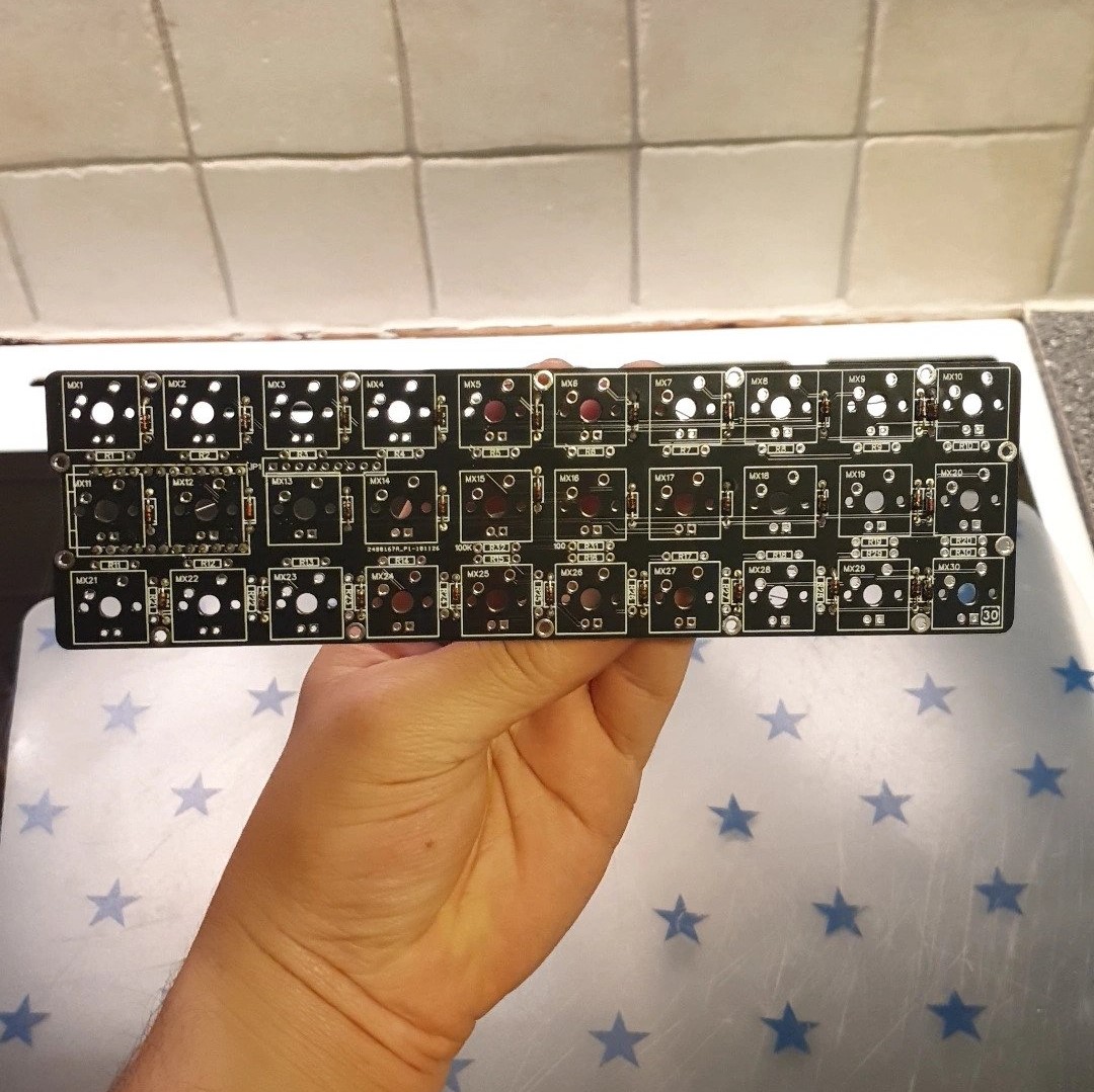 The front of the PCB before any soldering
I started by soldering the rails for the pro micro first. This was super easy and all you need to remember is to have the shorter legs go through the PCB rather than the long ones.
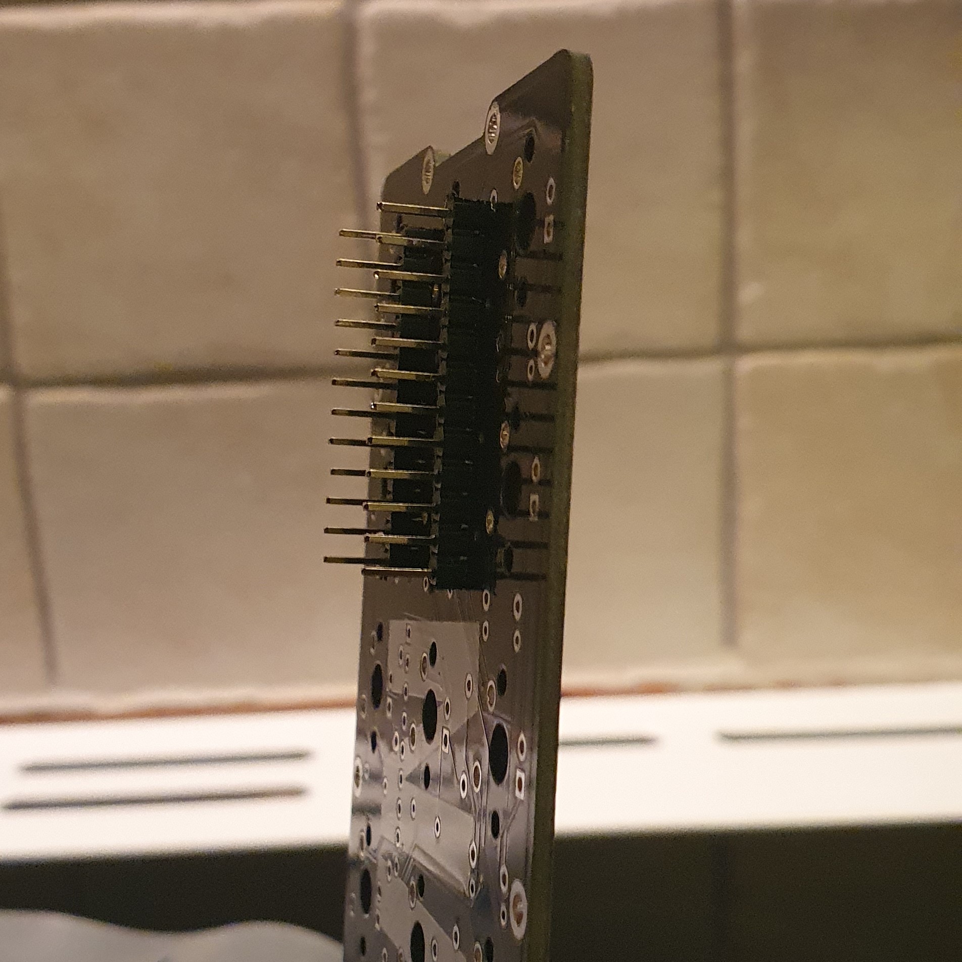 The rails that will eventually fit the Pro Micro chip
Then by far the most time consuming step of the entire project is soldering all 30 1n4148 diodes onto the board. They are soldered on the top of the board and you need to make sure they are in the right direction (the diodes have a black stripe on one side which is matched by a stripe on the PCB itself to indicate direction).
After soldering each diode, the legs that poke out the back side are trimmed to length. This is where having good mastery of soldering is ideal as a good solder means you can trim the legs really short. This is important as to not scratch the inside of the case, and near the Pro Micro slot is important so that you don’t accidentally poke it and short circuit the board.
In my build I messed up my solder a bit and had to make sure to slide the Pro Micro up slightly to avoid touching.
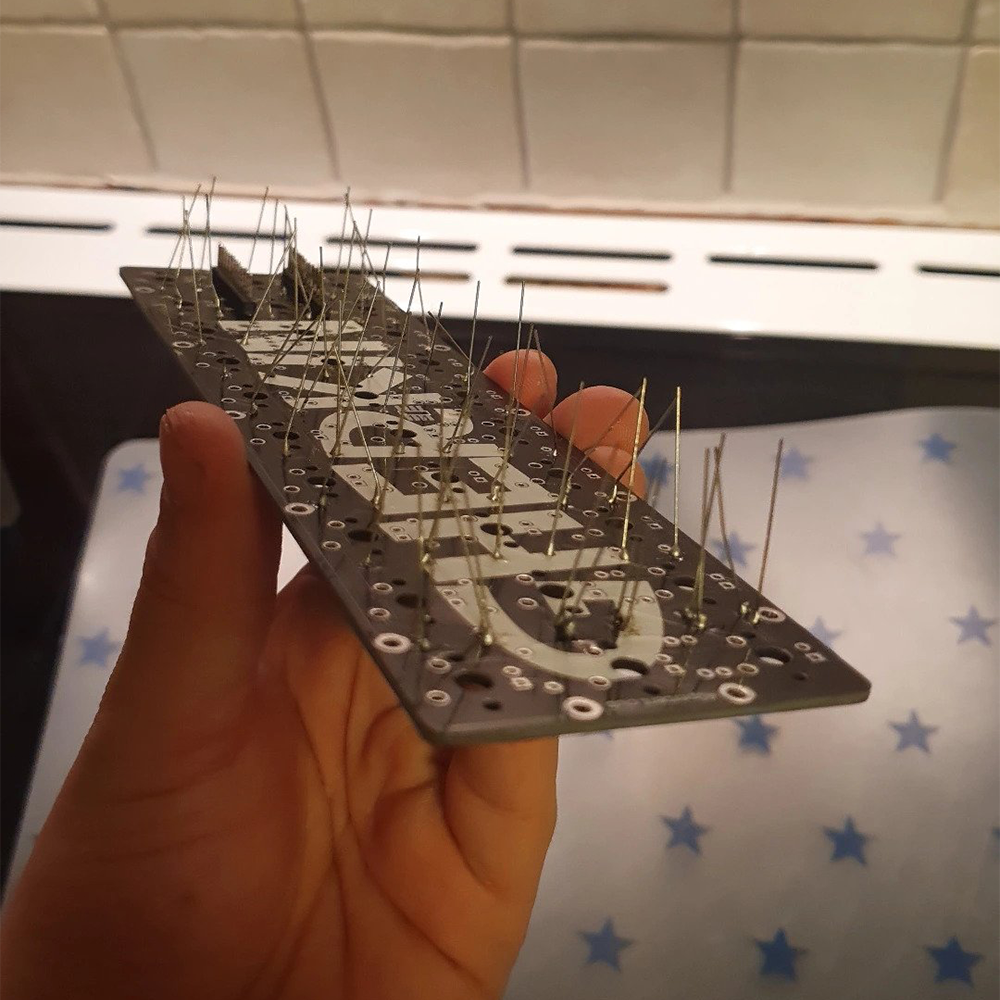 All the diodes soldered in place
Before the final step of the soldering process, the switches still needed to be put into place. The simplest way I found to do this was to find the correct acrylic layer that has exact holes for the switches on them. Then you simply place one switch in a corner, making sure neither of the legs are bent under the switch and instead go through the PCB hole. The legs are very short on the switches and as such you have to make sure they go through all the way or you won’t be able to solder them properly. Then repeat the step for the 3 remaining corners, still making sure that all the legs are unbent and go through the hole.
Then it is simply a matter of filling in the rest of the slots with switches you want, each time making sure the legs go through, and then soldering that on before moving on to the next switch. When I did this, I put the rest of the switches in before soldering as they click onto the top plate, the downside to this is that you have to put pressure on the switch when soldering to ensure that the legs still poke through the PCB.
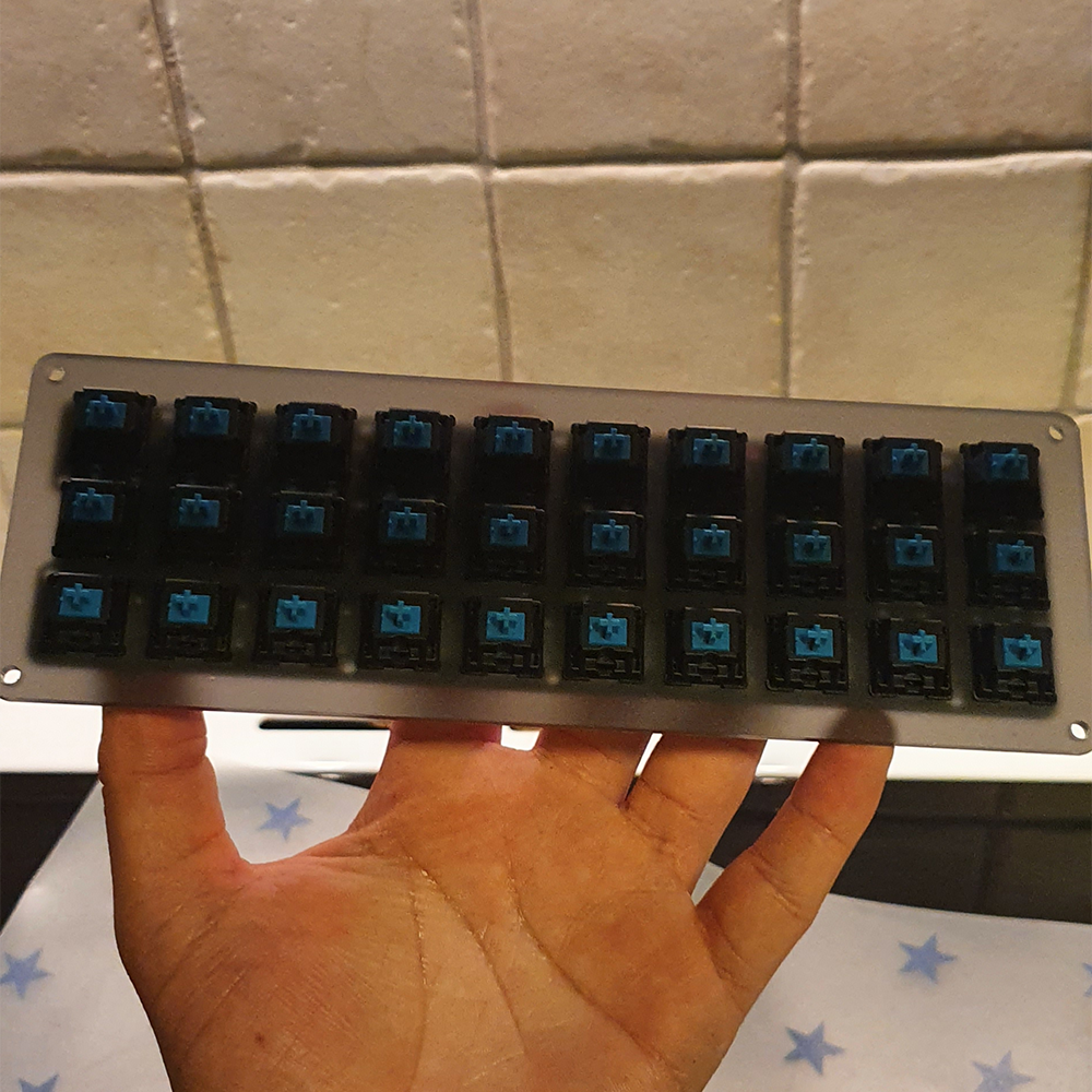 Finally the switches in place and soldered
For the final soldering step, all I had to do was put the Pro Micro in place, make sure it didn’t touch the legs that are directly below it and then solder it in place. Once again, soldering the corners first for stability before soldering the rest. I’m not sure if it applies to every version of the gherkin, but at least for my build, the correct direction to put the Pro Micro was with the micro-USB slot facing inwards towards the gherkin PCB.
In this part of the project I decided to close up the case. It was a very simple game of matching the acrylic plates to create the right shape. The case in its final form has a slightly curved shape to it when seen from the front and sides. It also came with these golden colored riser things that insert into the middle layers but are blocked by the 2 outermost layers as they have smaller holes. The smaller holes on the top and bottom layers makes it very intuitive to figure out how to build as the holes are only big enough to fit the screws.
The case was all put together and the keyboard only needed to be flashed with the right firmware before adding the keycaps. However I had completely forgotten that to flash the pro micro, you need to short the reset and ground pins on the board, which now was unavailable as it was inside the case. I then had to partially take apart the case to access the pro micro. The next step was to first decide on a keymap before compiling it and flashing it to the board.
The first thing I did was go to the QMK configurator website and selecting the gherkin layout under the “keyboard” dropdown. Then I set up the layout the way I wanted it before naming the layout and hitting the compile button. Then I downloaded the compiled firmware which is saved as a .hex file on your computer. After this I downloaded QMK toolbox which was used to flash the firmware onto the Pro Micro.
Then once I had QMK toolbox running I hit the open button on the top and selected my .hex file. Then I plugged in my keyboard and with QMK toolbox still running I shorted the ground and reset pin on the Pro Micro. Depending on which version you use, the reset pin might be hard to see so it’s important to check that you have the right pins before shorting them. This will give you a short window to flash it with QMK toolbox. The software will let you know when you can flash the keyboard with a yellow text that shows up inside the console. You then have to quickly hit the “flash” button in the toolbox. It will flash for a little bit before letting you know at the bottom “avrdude.exe done. thank you” before the yellow text lets you know the Pro micro has been disconnected.
I then used an online keyboard tester to test that all the keys were working before finally putting on the keycaps. My keycaps were a set of 30 white dsa keycaps as well as 5 pacman themed ones which I got from the same store on aliexpress. This was the final step before the keyboard was ready to use.
Final thoughts
This project was a lot of fun to do and I really enjoyed building and soldering a keyboard from scratch again as I haven’t done that in a long time. The keyboard itself sees daily use as I use it to lower and increase volume on my computer. It is also especially helpful when using software thats meant to be used with a numpad as my daily driver is a 60% and i prefer using the macropad rather than using the layer function on the 60%. Since it sees alot less use than my main keyboard the clicking sound from the blue switches becomes alot more bearable and feels very fun to use whenever I need it, a sentiment I would not have if I had to use it for typing.